 |
The OpenVX Specification
dba1aa3
|
|
The OpenVX Specification
dba1aa3
|
OpenVX is intended to be used either directly by applications or as the acceleration layer for higher-level vision frameworks, engines or platform APIs.
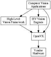
OpenVX is designed as a framework of standardized computer vision functions able to run on a wide variety of platforms and potentially to be accelerated by a vendor's implementation on that platform. OpenVX can improve the performance and efficiency of vision applications by providing an abstraction for commonly-used vision functions and an abstraction for aggregations of functions (a “graph”), thereby providing the implementer the opportunity to minimize the run-time overhead.
The functions in OpenVX are intended to cover common functionality required by many vision applications.
This specification makes no statements as to which acceleration methodology or techniques may be used in its implementation. Vendors may choose any number of implementation methods such as parallelism and/or specialized hardware offload techniques.
This specification also makes no statement or requirements on a “level of performance” as this may vary significantly across platforms and use cases.
The OpenVX focuses on vision functions that can be significantly accelerated by diverse hardware. Future versions of this specification may adopt additional vision functions into the core standard when hardware acceleration for those functions becomes practical.
OpenVX has been designed to maximize functional and performance portability wherever possible, while recognizing that the API is intended to be used on a wide diversity of devices with specific constraints and properties. Tradeoffs are made for portability where possible: for example, portable Graphs constructed using this API should work on any OpenVX implementation and return similar results within the precision bounds defined by the OpenVX conformance tests.
OpenVX is intended to address a very broad range of devices and platforms, from deeply embedded systems to desktop machines and distributed computing architectures. The OpenVX API addresses this range of possible implementations without forcing hardware-specific requirements onto any particular implementation via the use of opaque objects for most program data.
All data, except client-facing structures, are opaque and hidden behind a reference that may be as thin or thick as an implementation needs. Each implementation provides the standardized interfaces for accessing data that takes care of specialized hardware, platform, or allocation requirements. Memory that is imported or shared from other APIs is not subsumed by OpenVX and is still maintained and accessible by the originator.
OpenVX does not dictate any requirements on memory allocation methods or the layout of opaque memory objects and it does not dictate byte packing or alignment for structures on architectures.
OpenVX objects are both strongly typed at compile-time for safety critical applications and are strongly typed at run-time for dynamic applications. Each object has its typedef'd type and its associated enumerated value in the vx_type_e list. Any object may be down-cast to a vx_reference safely to be used in functions that require this, specifically vxQueryReference, which can be used to get the vx_type_e value using an vx_enum.
This specification defines the following OpenVX framework objects.
VX_TYPE_IMAGE, or VX_TYPE_ARRAY, or some other object type from vx_type_e. VX_INPUT, VX_OUTPUT, or VX_BIDIRECTIONAL. VX_PARAMETER_STATE_REQUIRED, or VX_PARAMETER_STATE_OPTIONAL.vx_parameter is extracted from a Node, an additional attribute can be accessed: vx_reference assigned to this parameter index from the Node creation function (e.g., vxSobel3x3Node).Data objects are object that are processed by graphs in nodes.
vx_int16 values. Also contains a scaling factor for normalization. Used specifically with vxuConvolve and vxConvolveNode.vx_df_image_e.vxTableLookupNode and vxuTableLookup.vx_image objects.vxHOGFeaturesNode, vxHOGCellsNode and the Neural Networks extension.Error objects are specialized objects that may be returned from other object creator functions when serious platform issue occur (i.e., out of memory or out of handles). These can be checked at the time of creation of these objects, but checking also may be put-off until usage in other APIs or verification time, in which case, the implementation must return appropriate errors to indicate that an invalid object type was used.
The graph is the central computation concept of OpenVX. The purpose of using graphs to express the Computer Vision problem is to allow for the possibility of any implementation to maximize its optimization potential because all the operations of the graph and its dependencies are known ahead of time, before the graph is processed.
Graphs are composed of one or more nodes that are added to the graph through node creation functions. Graphs in OpenVX must be created ahead of processing time and verified by the implementation, after which they can be processed as many times as needed.
Graph Nodes are linked together via data dependencies with no explicitly-stated ordering. The same reference may be linked to other nodes. Linking has a limitation, however, in that only one node in a graph may output to any specific data object reference. That is, only a single writer of an object may exist in a given graph. This prevents indeterminate ordering from data dependencies. All writers in a graph shall produce output data before any reader of that data accesses it.
Graphs in OpenVX depend on data objects to link together nodes. When clients of OpenVX know that they do not need access to these intermediate data objects, they may be created as virtual. Virtual data objects can be used in the same manner as non-virtual data objects to link nodes of a graph together; however, virtual data objects are different in the following respects.
These restrictions enable vendors the ability to optimize some aspects of the data object or its usage. Some vendors may not allocate such objects, some may create intermediate sub-objects of the object, and some may allocate the object on remote, inaccessible memories. OpenVX does not proscribe which optimization the vendor does, merely that it may happen.
Parameters to node creation functions are defined as either atomic types, such as vx_int32, vx_enum, or as objects, such as vx_scalar, vx_image. The atomic variables of the Node creation functions shall be converted by the framework into vx_scalar references for use by the Nodes. A node parameter of type vx_scalar can be changed during the graph execution; whereas, a node parameter of an atomic type (vx_int32 etc.) require at least a graph revalidation if changed. All node parameter objects may be modified by retrieving the reference to the vx_parameter via vxGetParameterByIndex, and then passing that to vxQueryParameter to retrieve the reference to the object.
If the type of the parameter is unknown, it may be retrieved with the same function.
Parameters may exist on Graphs, as well. These parameters are defined by the author of the Graph and each Graph parameter is defined as a specific parameter from a Node within the Graph using vxAddParameterToGraph. Graph parameters communicate to the implementation that there are specific Node parameters that may be modified by the client between Graph executions. Additionally, they are parameters that the client may set without the reference to the Node but with the reference to the Graph using vxSetGraphParameterByIndex. This allows for the Graph authors to construct Graph Factories. How these factories work falls outside the scope of this document.
Graphs must execute in both:
vxProcessGraph will block until the graph has completed), and invxScheduleGraph and vxWaitGraph).In asynchronous mode, Graphs must be single-issue-per-reference. This means that given a constructed graph reference \(G\), it may be scheduled multiple times but only executes sequentially with respect to itself. Multiple graphs references given to the asynchronous graph interface do not have a defined behavior and may execute in parallel or in series based on the behavior or the vendor's implementation.
To use graphs several rules must be put in place to allow deterministic execution of Graphs. The behavior of a processGraph( \(G\)) call is determined by the structure of the Processing Graph \(G\). The Processing Graph is a bipartite graph consisting of a set of Nodes \(N_1 \ldots N_n\) and a set of data objects \(d_1 \ldots d_i\). Each edge ( \(N_x\), \(D_y\)) in the graph represents a data object \(D_y\) that is written by Node \(N_x\) and each edge ( \(D_x\), \(N_y\)) represents a data object \(D_x\) that is read by Node \(N_y\). Each edge \(e\) has a name Name( \(e\)), which gives the parameter name of the node that references the corresponding data object. Each Node Parameter also has a type Type(node, name) in {INPUT, OUTPUT, INOUT}. Some data objects are Virtual, and some data objects are Delay. Delay data objects are just collections of data objects with indexing (like an image list) and known linking points in a graph. A node may be classified as a head node, which has no backward dependency. Alternatively, a node may be a dependent node, which has a backward dependency to the head node. In addition, the Processing Graph has several restrictions:
Type( \(N_x\), Name( \(N_x\), \(D_y\))) in {OUTPUT, INOUT} Type( \(N_y\), Name( \(D_x\), \(N_y\))) in {INPUT} or {INOUT} Type( \(N_x\), Name( \(N_x\), \(D_y\))) is INOUT implies \(D_y\) is non-Virtual. The execution of each node in a graph consists of an atomic operation (sometimes referred to as firing) that consumes data representing each input data object, processes it, and produces data representing each output data object. A node may execute when all of its input edges are marked present. Before the graph executes, the following initial marking is used:
Processing a node results in unmarking all the corresponding input edges and marking all its output edges; marking an output edge ( \(N_x\), \(D_y\)) where \(D_y\) is not a Delay results in marking all of the input edges ( \(D_y\), \(N_z\)). Following these rules, it is possible to statically schedule the nodes in a graph as follows: Construct a precedence graph \(P\), including all the nodes \(N_1 \ldots N_x\), and an edge ( \(N_x\), \(N_z\)) for every pair of edges ( \(N_x\), \(D_y\)) and ( \(D_y\), \(N_z\)) where \(D_y\) is not a Delay. Then unconditionally fire each node according to any topological sort of \(P\).
The following assertions should be verified:
The execution model described here just acts as a formalism. For example, independent processing is allowed across multiple depended and depending nodes and edges, provided that the result is invariant with the execution model described here.
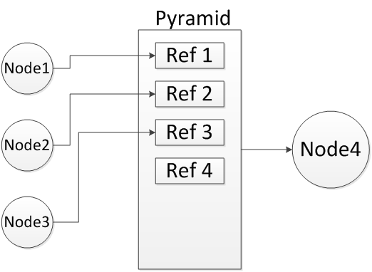
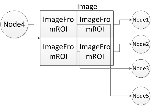
There are cases in which two different data objects referenced by an output parameter of node \(N_1\) and input parameter of node \(N_2\) in a graph induce a dependency between these two nodes: For example, a pyramid and its level images, image and the sub-images created from it by vxCreateImageFromROI or vxCreateImageFromChannel, or overlapping sub-images of the same image. Following figure show examples of this dependency. To simplify subsequent definitions and requirements a limitation is imposed that if a sub-image I' has been created from image I and sub-image I'' has been created from I', then I'' is still considered a sub-image of I and not of I'. In these cases it is expected that although the two nodes reference two different data objects, any change to one data object might be reflected in the other one. Therefore it implies that \(N_1\) comes before \(N_2\) in the graph's topological order. To ensure that, following definitions are introduced.
\begin{eqnarray} C_i(d)=\bigcup_{d'\in{C_{i-1}(d)}}C_1(d') \end{eqnarray}
\begin{eqnarray} C(d)=\bigcup_{i=0}^{\infty}C_i(d) \end{eqnarray}

\begin{eqnarray} d_1\in{C(d_2)}\ or\ d_2\in{C(d_1)}\ or\ (I(d_1)\ and\ I(d_2)\ and\ d_1R_{ov}d_2) \end{eqnarray}
If data object \(D_y\) of an output edge ( \(N_x\), \(D_y\)) overlaps with a data object \(D_z\) then the result is implementation defined.
In the following example a client computes the gradient magnitude and gradient phase from a blurred input image. The vxMagnitudeNode and vxPhaseNode are independently computed, in that each does not depend on the output of the other. OpenVX does not mandate that they are run simultaneously or in parallel, but it could be implemented this way by the OpenVX vendor.

The code to construct such a graph can be seen below.
Graphs within OpenVX must go through a rigorous validation process before execution to satisfy the design concept of eliminating run-time overhead (parameter checking) that guarantees safe execution of the graph. OpenVX must check for (but is not limited to) these conditions:
Parameters To Nodes:
vx_direction_e). vx_type_e). vxScaleImageNode, the relation of the input image dimensions to the output image dimensions determines the scaling factor. These values or attributes of data objects must be checked for compatibility on each platform. vx_graph must be a Directed Acyclic Graph (DAG). No cycles or feedback is allowed. The vx_delay object has been designed to explicitly address feedback between Graph executions. The implementation must check that all node parameters are the correct type at node creation time, unless the parameter value is set to NULL. Additional checks may also be made on non-NULL parameters. The user must be allowed to set parameters to NULL at node creation time, even if they are required parameters, in order to create "exemplar" nodes that are not used in graph execution, or to create nodes incrementally. Therefore the implementation must not generate an error at node creation time for parameters that are explicitly set to NULL. However, the implementation must check that all required parameters are non-NULL and the correct type during vxVerifyGraph. Other more complex checks may also be done during vxVerifyGraph. The implementation should provide specific error reporting of NULL parameters during vxVerifyGraph, e.g., "Parameter<parameter> of Node<node> is NULL."
Callbacks are a method to control graph flow and to make decisions based on completed work. The vxAssignNodeCallback call takes as a parameter a callback function. This function will be called after the execution of the particular node, but prior to the completion of the graph. If nodes are arranged into independent sets, the order of the callbacks is unspecified. Nodes that are arranged in a serial fashion due to data dependencies perform callbacks in order. The callback function may use the node reference first to extract parameters from the node, and then extract the data references. Data outputs of Nodes with callbacks shall be available (via Map/Unmap/Copy methods) when the callback is called.
OpenVX supports the concept of client-defined functions that shall be executed as Nodes from inside the Graph or are Graph internal. The purpose of this paradigm is to:

In this example, to execute client-supplied functions, the graph does not have to be halted and then resumed. These nodes shall be executed in an independent fashion with respect to independent base nodes within OpenVX. This allows implementations to further minimize execution time if hardware to exploit this property exists.
User Kernels must aid in the Graph Verification effort by providing an explicit validation function for each vision function they implement. Each parameter passed to the instanced Node of a User Kernel is validated using the client-supplied validation function. The client must check these attributes and/or values of each parameter:
The Meta Format Object is an opaque object used to collect requirements about the output parameter, which then the OpenVX implementation will check. The Client must manually set relevant object attributes to be checked against output parameters, such as dimensionality, format, scaling, etc.
User Kernels must be exported with a unique name (see Naming Conventions for information on OpenVX conventions) and a unique enumeration. Clients of OpenVX may use either the name or enumeration to retrieve a kernel, so collisions due to non-unique names will cause problems. The kernel enumerations may be extended by following this example:
Each vendor of a vision function or an implementation must apply to Khronos to get a unique identifier (up to a limit of \( 2^{12}-1 \) vendors). Until they obtain a unique ID vendors must use VX_ID_DEFAULT.
To construct a kernel enumeration, a vendor must have both their ID and a library ID. The library ID's are completely vendor defined (however when using the VX_ID_DEFAULT ID, many libraries may collide in namespace).
Once both are defined, a kernel enumeration may be constructed using the VX_KERNEL_BASE macro and an offset. (The offset is optional, but very helpful for long enumerations.)
OpenVX also contains an interface defined within <VX/vxu.h> that allows for immediate execution of vision functions. These interfaces are prefixed with vxu to distinguish them from the Node interfaces, which are of the form vx<Name>Node. Each of these interfaces replicates a Node interface with some exceptions. Immediate mode functions are defined to behave as Single Node Graphs, which have no leaking side-effects (e.g., no Log entries) within the Graph Framework after the function returns. The following tables refer to both the Immediate Mode and Graph Mode vision functions. The Module documentation for each vision function draws a distinction on each API by noting that it is either an immediate mode function with the tag [Immediate] or it is a Graph mode function by the tag [Graph].
A 'Target' specifies a physical or logical devices where a node or an immediate mode function is executed. This allows the use of different implementations of vision functions on different targets. The existence of allowed Targets is exposed to the applications by the use of defined APIs. The choice of a Target allows for different levels of control on where the nodes can be executed. An OpenVX implementation must support at least one target. Additional supported targets are specified using the appropriate enumerations. See vxSetNodeTarget, vxSetImmediateModeTarget, and vx_target_e. An OpenVX implementation must support at least one target VX_TARGET_ANY as well as VX_TARGET_STRING enumerates. An OpenVX implementation may also support more than these two to indicate the use of specific devices. For example, an implementation may add VX_TARGET_CPU and VX_TARGET_GPU enumerates to indicate the support of two possible targets to assign a nodes to (or to excute an immediate mode function). Another way an implementation can indicate the existence of multiple targets, for example CPU and GPU, is by specifying the target as VX_TARGET_STRING and using strings 'CPU' and 'GPU'. Thus defining targets using names rather than enumerates. The specific naming of string or enumerates is not enforced by the specification and it is up to the vendors to document and communicate the Target naming. Once available in a given implementation Applications can assign a Target to a node to specify the target that must execute that node by using the API vxSetNodeTarget. For immediate mode functions the target specifies the physical or logical device where the future execution of that function will be attempted. When an immediate mode function is not supported on the selected target the execution falls back to VX_TARGET_ANY.
OpenVX comes with a standard or base set of vision functions. The following table lists the supported set of vision functions, their input types (first table) and output types (second table), and the version of OpenVX in which they are supported.
| Vision Function | S8 | U8 | U16 | S16 | U32 | F32 | color | other |
|---|---|---|---|---|---|---|---|---|
| AbsDiff | 1.0 | 1.0.1 | ||||||
| Accumulate | 1.0 | |||||||
| AccumulateSquared | 1.0 | |||||||
| AccumulateWeighted | 1.0 | |||||||
| Add | 1.0 | 1.0 | ||||||
| And | 1.0 | |||||||
| BilateralFilter | 1.2 | 1.2 | ||||||
| Box3x3 | 1.0 | |||||||
| CannyEdgeDetector | 1.0 | |||||||
| ChannelCombine | 1.0 | |||||||
| ChannelExtract | 1.0 | |||||||
| ColorConvert | 1.0 | |||||||
| ConvertDepth | 1.0 | 1.0 | ||||||
| Convolve | 1.0 | |||||||
| Data Object Copy | 1.2 | |||||||
| Dilate3x3 | 1.0 | |||||||
| EqualizeHistogram | 1.0 | |||||||
| Erode3x3 | 1.0 | |||||||
| FastCorners | 1.0 | |||||||
| Gaussian3x3 | 1.0 | |||||||
| GaussianPyramid | 1.1 | |||||||
| HarrisCorners | 1.0 | |||||||
| HalfScaleGaussian | 1.0 | |||||||
| Histogram | 1.0 | |||||||
| HOGCells | 1.2 | |||||||
| HOGFeatures | 1.2 | |||||||
| HoughLinesP | 1.2 | |||||||
| IntegralImage | 1.0 | |||||||
| LaplacianPyramid | 1.1 | |||||||
| LaplacianReconstruct | 1.1 | |||||||
| LBP | 1.2 | |||||||
| Magnitude | 1.0 | |||||||
| MatchTemplate | 1.2 | |||||||
| MeanStdDev | 1.0 | |||||||
| Median3x3 | 1.0 | |||||||
| Max | 1.2 | 1.2 | ||||||
| Min | 1.2 | 1.2 | ||||||
| MinMaxLoc | 1.0 | 1.0 | ||||||
| Multiply | 1.0 | 1.0 | ||||||
| NonLinearFilter | 1.1 | |||||||
| NonMaximaSuppression | 1.2 | 1.2 | ||||||
| Not | 1.0 | |||||||
| OpticalFlowPyrLK | 1.0 | |||||||
| Or | 1.0 | |||||||
| Phase | 1.0 | |||||||
| GaussianPyramid | 1.0 | |||||||
| Remap | 1.0 | |||||||
| ScaleImage | 1.0 | |||||||
| Sobel3x3 | 1.0 | |||||||
| Subtract | 1.0 | 1.0 | ||||||
| TableLookup | 1.0 | 1.1 | ||||||
| TensorMultiply | 1.2 | 1.2 | 1.2 | |||||
| TensorAdd | 1.2 | 1.2 | 1.2 | |||||
| TensorSubtract | 1.2 | 1.2 | 1.2 | |||||
| TensorMatrixMultiply | 1.2 | 1.2 | 1.2 | |||||
| TensorTableLookup | 1.2 | 1.2 | 1.2 | |||||
| TensorTranspose | 1.2 | 1.2 | 1.2 | |||||
| Threshold | 1.0 | |||||||
| WarpAffine | 1.0 | |||||||
| WarpPerspective | 1.0 | |||||||
| Xor | 1.0 |
| Vision Function | S8 | U8 | U16 | S16 | U32 | F32 | color | other |
|---|---|---|---|---|---|---|---|---|
| AbsDiff | 1.0 | 1.0.1 | ||||||
| Accumulate | 1.0 | |||||||
| AccumulateSquared | 1.0 | |||||||
| AccumulateWeighted | 1.0 | |||||||
| Add | 1.0 | 1.0 | ||||||
| And | 1.0 | |||||||
| BilateralFilter | 1.2 | 1.2 | ||||||
| Box3x3 | 1.0 | |||||||
| CannyEdgeDetector | 1.0 | |||||||
| ChannelCombine | 1.0 | |||||||
| ChannelExtract | 1.0 | |||||||
| ColorConvert | 1.0 | |||||||
| ConvertDepth | 1.0 | 1.0 | ||||||
| Convolve | 1.0 | 1.0 | ||||||
| Data Object Copy | 1.2 | |||||||
| Dilate3x3 | 1.0 | |||||||
| EqualizeHistogram | 1.0 | |||||||
| Erode3x3 | 1.0 | |||||||
| FastCorners | 1.0 | |||||||
| Gaussian3x3 | 1.0 | |||||||
| GaussianPyramid | 1.1 | |||||||
| HarrisCorners | 1.0 | |||||||
| HalfScaleGaussian | 1.0 | |||||||
| Histogram | 1.0 | |||||||
| HOGCells | 1.2 | 1.2 | ||||||
| HOGFeatures | 1.2 | 1.2 | ||||||
| HoughLinesP | 1.2 | |||||||
| IntegralImage | 1.0 | |||||||
| LaplacianPyramid | 1.1 | |||||||
| LaplacianReconstruct | 1.1 | |||||||
| LBP | 1.2 | |||||||
| Magnitude | 1.0 | |||||||
| MatchTemplate | 1.2 | |||||||
| MeanStdDev | 1.0 | |||||||
| Median3x3 | 1.0 | |||||||
| Max | 1.2 | 1.2 | ||||||
| Min | 1.2 | 1.2 | ||||||
| MinMaxLoc | 1.0 | 1.0 | 1.0 | |||||
| Multiply | 1.0 | 1.0 | ||||||
| NonLinearFilter | 1.1 | |||||||
| NonMaximaSuppression | 1.2 | 1.2 | ||||||
| Not | 1.0 | |||||||
| OpticalFlowPyrLK | ||||||||
| Or | 1.0 | |||||||
| Phase | 1.0 | |||||||
| GaussianPyramid | 1.0 | |||||||
| Remap | 1.0 | |||||||
| ScaleImage | 1.0 | |||||||
| Sobel3x3 | 1.0 | |||||||
| Subtract | 1.0 | 1.0 | ||||||
| TableLookup | 1.0 | 1.1 | ||||||
| TensorMultiply | 1.2 | 1.2 | 1.2 | |||||
| TensorAdd | 1.2 | 1.2 | 1.2 | |||||
| TensorSubtract | 1.2 | 1.2 | 1.2 | |||||
| TensorMatrixMultiply | 1.2 | 1.2 | 1.2 | |||||
| TensorTableLookup | 1.2 | 1.2 | 1.2 | |||||
| TensorTranspose | 1.2 | 1.2 | 1.2 | |||||
| Threshold | 1.0 | |||||||
| WarpAffine | 1.0 | |||||||
| WarpPerspective | 1.0 | |||||||
| Xor | 1.0 |
For vision functions, the input and output parameter ordering convention is:
The known exceptions are:
The lifecycle of the context is very simple.

OpenVX has four main phases of graph lifecycle:
vxCreateGraph, and Nodes are connected together by data objects. vxProcessGraph or vxScheduleGraph. Between executions data may be updated by the client or some other external mechanism. The client of OpenVX may change reference of input data to a graph, but this may require the graph to be validated again by checking vxIsGraphVerified. vxReleaseGraph. All Nodes in the Graph are released.
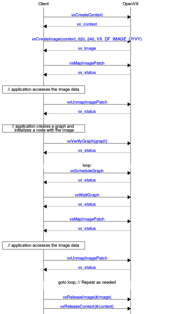
All objects in OpenVX follow a similar lifecycle model. All objects are
vxCreate<Object><Method> or retreived via vxGet<Object><Method> from the parent object if they are internally created. vxRelease<Object> or via vxReleaseContext when all objects are released.This is an example of the Image Lifecycle using the OpenVX Framework API. This would also apply to other data types with changes to the types and function names.
For objects retrieved from OpenVX that are 2D in nature, such as vx_image, vx_matrix, and vx_convolution, the manner in which the host-side has access to these memory regions is well-defined. OpenVX uses a row-major storage (that is each unit in a column is memory-adjacent to its row adjacent unit). Two-dimensional objects are always created (using vxCreateImage or vxCreateMatrix) in width (columns) by height (rows) notation, with the arguments in that order. When accessing these structures in “C” with two-dimensional arrays of declared size, the user must therefore provide the array dimensions in the reverse of the order of the arguments to the Create function. This layout ensures row-wise storage in C on the host. A pointer could also be allocated for the matrix data and would have to be indexed in this row-major method.
Images and Array differ slightly in how they are accessed due to more complex memory layout requirements.
Arrays only require a single value, the stride, instead of the entire addressing structure that images need.
Map/Unmap pairs can also be called on individual elements of array using a method similar to this:
Accessing OpenVX data-objects using the functions Map, Copy, Read concurrently to an execution of a graph that is accessing the same data objects is permitted only if all accesses are read-only. That is, for Map, Copy to have a read-only access mode and for nodes in the graph to have that data-object as an input parameter only. In all other cases, including write or read-write modes and Write access function, as well as a graph nodes having the data-object as output or bidirectional, the application must guarantee that the access is not performed concurrently with the graph execution. That can be achieved by calling un-map following a map before calling vxScheduleGraph or vxProcessGraph. In addition, the application must call vxWaitGraph after vxScheduleGraph before calling Map, Read, Write or Copy to avoid restricted concurrent access. An application that fails to follow the above might encounter an undefined behavior and/or data loss without being notified by the OpenVX framework. Accessing images created from ROI (vxCreateImageFromROI) or created from a channel (vxCreateImageFromChannel) must be treated as if the entire image is being accessed.
The valid region mechanism informs the application as to which pixels of the output images of a graph's execution have valid values (see valid pixel definition below). The mechanism also applies to immediate mode (VXU) calls, and supports the communication of the valid region between different graph executions. Some vision functions, mainly those providing statistics and summarization of image information, use the valid region to ignore pixels that are not valid on their inputs (potentially bad or unstable pixel values). A good example of such a function is Min/Max Location. Formalization of the valid region mechanism is given below.
VX_BORDER_UNDEFINED VX_NODE_VALID_RECT_RESET is a read only attribute and is used to communicate valid rectangle reset behavior to the application. When it is set to vx_true_e for a given node the valid rectangle of the output images will reset to the full image upon execution of the node, when it is set to vx_false_e the valid rectangle will be calculated. All standard OpenVX functions will have this attribute set to vx_false_e by default, except for Warp and Remap where it will be set to vx_true_e.vxCreateImageFromROI; in that case, the valid region of the ROI image is the subset of the valid region of the parent image that is within the ROI. In other words, the valid region of an image created using an ROI is the largest rectangle that contains valid pixels in the parent image.vxSetImageValidRectangle. Notice that using vxMapImagePatch, vxUnmapImagePatch or vxSwapImageHandle does not change the valid region of an image. If a non-UNDEFINED border mode is used on an image where the valid region is not the full image, the results at the border and resulting size of the valid region are implementation-dependent. This case can occur when mixing UNDEFINED and other border mode, which is not recommended.vxGetValidRegionImage.vx_meta_format attribute VX_VALID_RECT_CALLBACK during the output validator. The callback function must be callable by the OpenVX framework during graph validation and execution. Assumptions must not be made regarding the order and the frequency by which the valid rectangle callback is called. The framework will recalculate the valid region when a change in the input valid regions is detected. For user nodes, the default value of VX_NODE_VALID_RECT_RESET is vx_true_e. Setting VX_VALID_RECT_CALLBACK during parameter validation to a value other than NULL will result in setting VX_NODE_VALID_RECT_RESET to vx_false_e. Note: the above means that when VX_VALID_RECT_CALLBACK is not set or set to NULL the user-node will reset the valid rectangle to the entire image.VX_NODE_VALID_RECT_RESET set to vx_true_e Beyond User Kernels there are other mechanisms for vendors to extend features in OpenVX. These mechanisms are not available to User Kernels. Each OpenVX official extension has a unique identifier, comprised of capital letters, numbers and the underscore character, prefixed with "KHR_", for example "KHR_NEW_FEATURE".
When extending attributes, vendors must use their assigned ID from vx_vendor_id_e in conjunction with the appropriate macros for creating new attributes with VX_ATTRIBUTE_BASE. The typical mechanism to extend a new attribute for some object type (for example a vx_node attribute from VX_ID_TI) would look like this:
Vendors wanting to add more kernels to the base set supplied to OpenVX should provide a header of the form
that contains definitions of each of the following.
Some extensions affect base vision functions and thus may be invisible to most users. In these circumstances, the vendor must report the supported extensions to the base nodes through the VX_CONTEXT_EXTENSIONS attribute on the context.
Extensions in this list are dependent on the extension itself; they may or may not have a header and new kernels or framework feature or data objects. The common feature is that they are implemented and supported by the implementation vendor.
The specification defines a Hinting API that allows Clients to feed information to the implementation for optional behavior changes. See Framework: Hints. It is assumed that most of the hints will be vendor- or implementation-specific. Check with the OpenVX implementation vendor for information on vendor-specific extensions.
The specification defines a Directive API to control implementation behavior. See Framework: Directives. This may allow things like disabling parallelism for debugging, enabling cache writing-through for some buffers, or any implementation-specific optimization.
The Khronos Group 2011-2017. OpenVX™, OpenCL™, OpenGL™, and OpenMAX™ are trademarks of the Khronos Group™.
Copyright © 2016-2017 The Khronos Group Inc. All Rights Reserved.
This specification is protected by copyright laws and contains material proprietary to the Khronos Group, Inc. It or any components may not be reproduced, republished, distributed, transmitted, displayed, broadcast or otherwise exploited in any manner without the express prior written permission of Khronos Group. You may use this specification for implementing the functionality therein, without altering or removing any trademark, copyright or other notice from the specification, but the receipt or possession of this specification does not convey any rights to reproduce, disclose, or distribute its contents, or to manufacture, use, or sell anything that it may describe, in whole or in part.
Khronos Group grants express permission to any current Promoter, Contributor or Adopter member of Khronos to copy and redistribute UNMODIFIED versions of this specification in any fashion, provided that NO CHARGE is made for the specification and the latest available update of the specification for any version of the API is used whenever possible. Such distributed specification may be re-formatted AS LONG AS the contents of the specification are not changed in any way. The specification may be incorporated into a product that is sold as long as such product includes significant independent work developed by the seller. A link to the current version of this specification on the Khronos Group web-site should be included whenever possible with specification distributions.
Khronos Group makes no, and expressly disclaims any, representations or warranties, express or implied, regarding this specification, including, without limitation, any implied warranties of merchantability or fitness for a particular purpose or non-infringement of any intellectual property. Khronos Group makes no, and expressly disclaims any, warranties, express or implied, regarding the correctness, accuracy, completeness, timeliness, and reliability of the specification. Under no circumstances will the Khronos Group, or any of its Promoters, Contributors or Members or their respective partners, officers, directors, employees, agents or representatives be liable for any damages, whether direct, indirect, special or consequential damages for lost revenues, lost profits, or otherwise, arising from or in connection with these materials.
Khronos, DevU, StreamInput, glTF, WebGL, WebCL, COLLADA, OpenKODE, OpenVG, OpenVX, OpenSL ES and OpenMAX are trademarks of the Khronos Group Inc. ASTC is a trademark of ARM Holdings PLC, OpenCL is a trademark of Apple Inc. and OpenGL is a registered trademark and the OpenGL ES and OpenGL SC logos are trademarks of Silicon Graphics International used under license by Khronos. All other product names, trademarks, and/or company names are used solely for identification and belong to their respective owners.
 1.8.11
